
08: Aplicações Laparoscópicas e Robóticas
Este capítulo levará aproximadamente 18 minutos para ler.
Breve histórico das aplicações laparoscópicas e robóticas em urologia pediátrica
A laparoscopia e a laparoscopia assistida por robô fazem parte da cirurgia minimamente invasiva, que tem se tornado cada vez mais popular no mundo. A história da laparoscopia remonta a 1805, quando Bozzini desenvolveu o primeiro cistoscópio. O termo laparoscopia (“laparothorakoskopie”) foi cunhado pelo cirurgião sueco Hans Christian Jacobaeus em 1901. No mesmo ano, ele relatou 17 casos de laparoscopia e 2 toracoscopias.1 A laparoscopia inicial apresentava muitas limitações e suscitou maiores preocupações pelo aumento significativo das taxas de complicações.
A técnica de vídeo começou a se desenvolver na década de 1960, o que ajuda os cirurgiões a visualizar o campo operatório em um monitor. O primeiro caso de técnica laparoscópica em urologia pediátrica foi para criptorquidia não palpável, relatado em 1976.2 Durante as décadas de 1970 e 1980, a laparoscopia teve aceitação ampla apenas para fins diagnósticos entre urologistas pediátricos. A fase seguinte da laparoscopia operatória ocorreu na década de 1990, quando procedimentos laparoscópicos mais complexos começaram a surgir, seguindo a prática da cirurgia de adultos. Em 1993, Kavoussi descreveu a primeira pieloplastia laparoscópica em uma mulher de 24 anos. Dois anos depois, Craig Peters relatou a primeira pieloplastia laparoscópica desmembrada para uma obstrução da junção ureteropélvica direita em um menino.3 A pieloplastia laparoscópica reduziu significativamente o tempo de internação e melhorou o controle da dor pós-operatória. Desde então, várias empresas como Karl Storz Endocsopy, Richard Wolf passaram a trabalhar com urologistas pediátricos para desenvolver e aprimorar instrumentos laparoscópicos.
Nas últimas décadas, a cirurgia laparoscópica tornou-se uma parte importante da prática urológica pediátrica. Em alguns casos, ela substituiu a cirurgia aberta convencional e, em vários, é reconhecida como a abordagem padrão-ouro. A cirurgia laparoscópica apresenta resultados comparáveis, ao mesmo tempo que reduz as incisões cirúrgicas a portos de 3 mm e 5 mm. Com o objetivo de ausência de cicatrizes, até mesmo a cirurgia endoscópica transluminal por orifícios naturais (NOTES) e a cirurgia laparoscópica por incisão única são possíveis e praticadas em alguns centros.4
Em 2000, a FDA aprovou um sistema cirúrgico robótico denominado da Vinci Surgical System, desenvolvido pela Intuitive Surgical. Ele é projetado para facilitar a cirurgia laparoscópica e é controlado por um cirurgião a partir de um console na sala de cirurgia. Apresenta as vantagens de uma visão 3D estável e ampliada, filtragem de tremor e escala de movimento para exposição e sutura intracorpóreas precisas. Nas últimas duas décadas, a cirurgia assistida por robô tem sido comumente utilizada em urologia, ginecologia, cirurgia geral e cirurgia pediátrica. O sistema cirúrgico da Vinci evoluiu da primeira geração, o modelo S, para o Si e, mais recentemente, para o Xi e para o sistema SP de porta única.
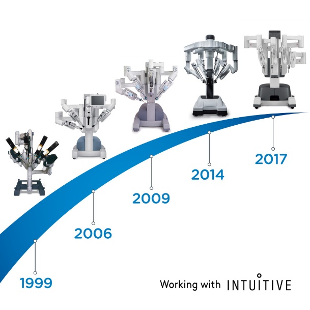
Figura 1 A evolução do Sistema Cirúrgico da Vinci
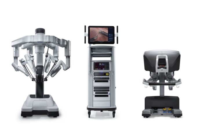
Figura 2 Sistema Cirúrgico da Vinci Xi
Em 2001, Meininger relatou o primeiro caso de fundoplicatura de Nissen assistida por robô em um paciente pediátrico.5 Esse trabalho inspirou o avanço da cirurgia pediátrica. A pieloplastia laparoscópica assistida por robô (RALP) foi a primeira cirurgia realizada com a plataforma da Vinci no campo da urologia pediátrica, relatada por Olsen e Jorgensen em 2004.6 Em 2005, Atug descreveu sua experiência com RALP em sete pacientes pediátricos com idades entre 6 e 15 anos.7 Em 2006, Lee comparou os resultados de RALP e da pieloplastia aberta (OP) pareando idade e sexo em 33 pacientes.8 Eles constataram que o tempo operatório médio foi de 219 minutos no grupo RALP, enquanto foi de apenas 181 minutos no grupo de procedimento aberto. O tempo operatório da RALP diminuiu significativamente após 15 casos. A coorte de RALP demonstrou menor tempo de internação, menor necessidade de medicação analgésica, e a taxa de sucesso foi de 93,9%.9 Dada a alta taxa de sucesso e a baixa taxa de complicações da RALP, alguns urologistas expandiram essa abordagem para lactentes. Recentemente, Andolfi divulgou sua série de casos de RALP em lactentes e demonstrou que a RALP é uma opção atraente de manejo para a obstrução da junção ureteropélvica (UPJO) em lactentes, pois apresenta desfechos bem-sucedidos, benefícios de redução do tempo de internação hospitalar e melhor cosmese.10 A equipe de Higganbotham chegou a realizar orquidopexia laparoscópica assistida por robô em um menino com testículos não descidos bilaterais.11
Atualmente, a orquiopexia laparoscópica e a ligadura alta laparoscópica do processo vaginal tornaram-se tratamentos rotineiros em todo o mundo. A cirurgia laparoscópica assistida por robô também se disseminou nos EUA, na Europa e na Ásia. Muitas outras empresas tentaram desenvolver sistemas de robôs cirúrgicos para desafiar a dominância do da Vinci Surgical Systems. Entre eles estão o sistema cirúrgico Senhance da TransEnterix, a Single Port Orifce Robotic Technology (SPORT) da Titan Medical, o Hinotori Surgical Robot System da Medicaroid, o REVO‑I Robotic Surgical System da Meere Company, o sistema cirúrgico Edge da Edge Medical Robotics e assim por diante. Dezenas de sistemas cirúrgicos robóticos ainda estão em processo de desenvolvimento.12 A demanda por cirurgia assistida por robô continua a aumentar. Novas tecnologias podem aprimorar as abordagens minimamente invasivas e melhorar as capacidades dos sistemas previamente estabelecidos. São necessários estudos futuros para avaliar mais detalhadamente os pontos fortes e fracos de cada dispositivo e plataforma cirúrgica robótica na sala de operações.13
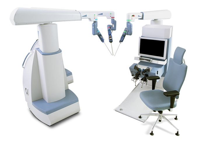
Figura 3 Sistema Cirúrgico Senhance
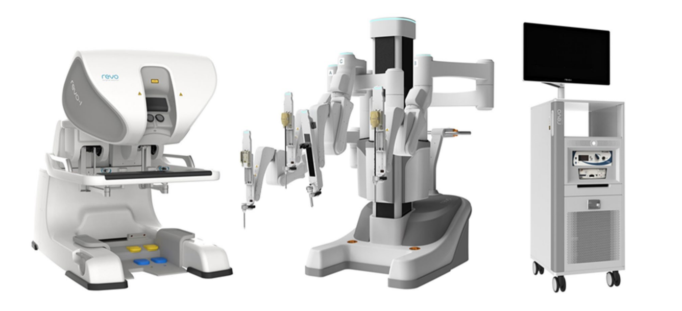
Figura 4 Sistema Robótico REVO-I
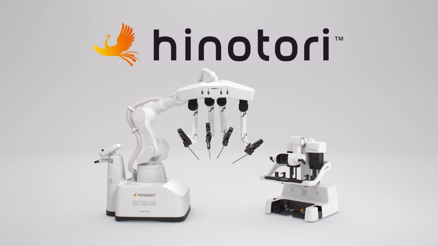
Figura 5 Sistema Robótico Hinotori
Instrumentos para Aplicações Laparoscópicas e Robóticas
Instrumentação da Cirurgia Urológica Laparoscópica Pediátrica
Equipamento para pneumoperitônio
Os equipamentos para pneumoperitônio consistem em aparelho de pneumoperitônio, cilindro de CO2, tubulação de saída de gás e instrumentos de punção. O aparelho de pneumoperitônio pode regular a pressão do pneumoperitônio (6–10 mm Hg) e o fluxo de gás. O aparelho de pneumoperitônio atual pode ajustar automaticamente a pressão intra-abdominal, injetar rapidamente gás e monitorar o consumo de CO2, estando equipado com dispositivos de alarme para pressão insuficiente de CO2 no cilindro ou pressão intra-abdominal excedendo a faixa predefinida, permitindo que o cirurgião detecte oportunamente quaisquer problemas, o que melhora a segurança da operação. Os aparelhos modernos de pneumoperitônio (Figura 6) podem alcançar: ① Circulação automática para filtrar a fumaça e assegurar um campo operatório claro; ② Monitoramento em tempo real da pressão do pneumoperitônio para assegurar pressão de pneumoperitônio constante; ③ Alguns equipamentos insufladores de pneumoperitônio possuem um sistema de aquecimento do gás para evitar a queda da temperatura corporal do paciente. ④ Eliminar as emissões de fumaça para a sala de operações, a fim de garantir a saúde de cirurgiões e enfermeiros.
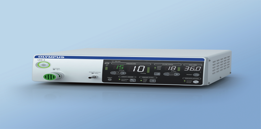
Figura 6 Máquina moderna de pneumoperitônio
Carrinho de energia
O carrinho de energia (Figura 7) integra o monitor, o aparelho de pneumoperitônio, o sistema de câmera, o sistema de fonte de luz e o bisturi elétrico em um único carrinho, que é fácil de empurrar e permite ao operador mudar a posição a qualquer momento.
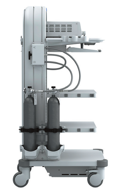
Figura 7 Carrinho de alimentação elétrica
Sistema Óptico
Atualmente, os laparoscópios utilizam principalmente sistemas ópticos de lentes em bastão, com boa transmissão de luz, imagens sem distorção, planas, ângulos ultra-amplos, brilho uniforme, grande profundidade de campo e forte sensação estereoscópica. O diâmetro é de 5–10 mm, o comprimento de trabalho é de 31 cm e o campo de visão é de 0˚, 30˚ e 45˚ (Figura 8). O laparoscópio de 30˚ com diâmetro de 5 mm é o laparoscópio mais comumente utilizado em urologia pediátrica, apresentando as vantagens de alterar o campo de visão cirúrgico, reduzir áreas cegas, permitir a observação da mesma estrutura a partir de diferentes ângulos, facilitar a formação de uma impressão tridimensional pelo cirurgião e reduzir a interferência mútua entre o laparoscópio e os instrumentos.
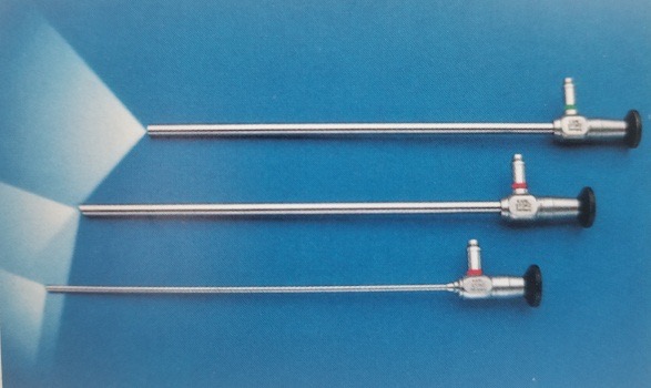
Figura 8 Os laparoscópios de 0°, 30° e 45°.
Fonte de luz fria e sonda de fibra óptica
Uma fonte de luz fria (Figura 7) fornece proporções iguais de luz nos comprimentos de onda vermelho, azul e verde para criar luz branca e é o tipo de luz mais comumente utilizado na cirurgia laparoscópica. Muitos dispositivos atualmente usam uma lâmpada de xenônio (300 W) ou lâmpada de xenônio com tecnologia LED acoplada ao ajuste automático de brilho para fornecer uma fonte de luz confiável durante a cirurgia. A vida média da lâmpada é de até até 3.000 horas. Esse tipo de fonte de luz é econômico, durável e eficiente. A sonda de fibra óptica na lente (Figura 8) é composta por um feixe flexível de fibras guia de luz com transmissão de luz de alta qualidade. Elas podem se romper com a deflexão ou a curvatura da lente e requerem reparo ou substituição.
Sistema de Câmera
O sistema de câmera laparoscópica (Figura 9) evoluiu de definição padrão para alta definição, para ultra-alta definição e, mais recentemente, para sistemas de câmeras 4K. Com a melhora da resolução, pode proporcionar ao operador imagens cirúrgicas mais nítidas. A tecnologia de laparoscópio 3D está disponível atualmente, mas apenas com diâmetro de 10 mm, portanto é menos comum em urologia pediátrica.
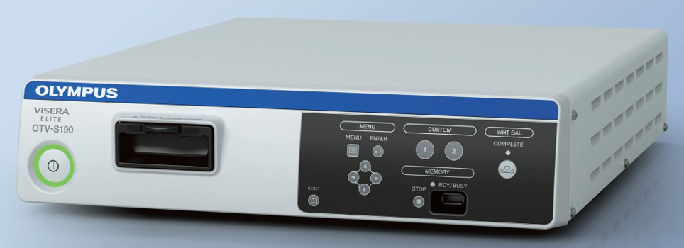
Figura 9 Sistema de câmera laparoscópica
Sistema eletrocirúrgico
Foram incluídos Electrodebrider e sistema de eletrocoagulação, bisturi ultrassônico (Harmonic scalpel), plataforma de energia e Ligasure. Esses dispositivos fornecem vários tipos de energia, incluindo eletrocautério monopolar, eletrocautério bipolar, energia ultrassônica e combinações para auxiliar os cirurgiões (Figura 10, Figura 11, Figura 12, e Figura 13).
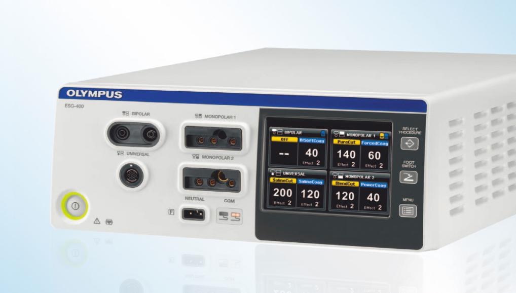
Figura 10 Unidade de eletrocirurgia
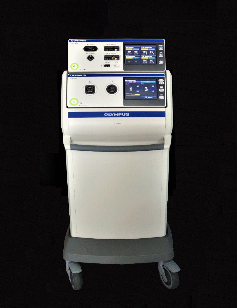
Figura 11 Bisturi ultrassónico
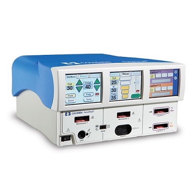
Figura 12 Plataforma de energia
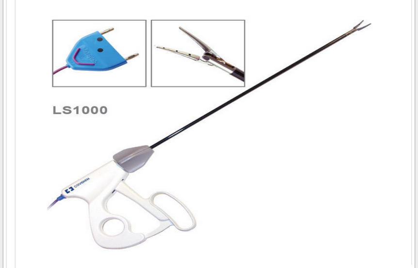
Figura 13 Ligasure
Outros Instrumentos
Os instrumentos comumente utilizados consistem em agulha de Veress, trocarte, aplicadores de clipes Hem-o-Lok, aplicadores de clipes de titânio, pinças de preensão, porta-agulhas, tesouras, entre outros (Figura 14, Figura 15, Figura 16).
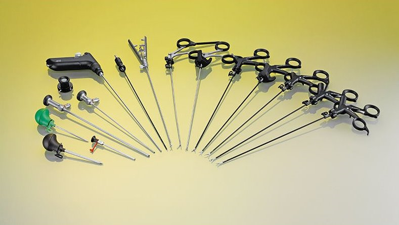
Figura 14 Instrumentos comuns
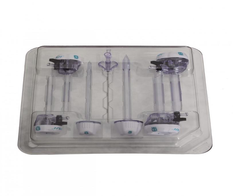
Figura 15 Trocarte
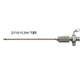
Figura 16 Agulha de Veress
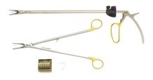
Figura 17 Aplicador de clipes Hem-o-lok
Instrumentação da Cirurgia Laparoscópica Assistida por Robô Da Vinci
O sistema cirúrgico da Vinci é composto principalmente por três partes: console do cirurgião, sistema de braço robótico à beira do leito (Patient Cart) e sistema de imagem 3D (Vision Cart), conforme mostrado na Figura 18.
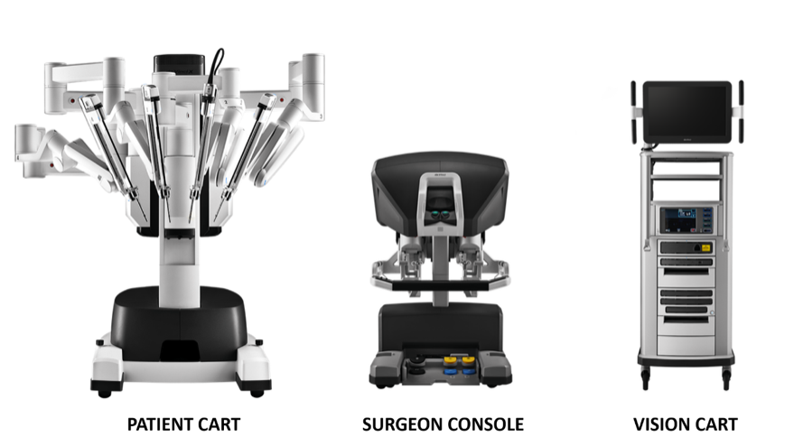
Figura 18 Três componentes que compõem o sistema da Vinci
Console Cirúrgico: Este console pode ser colocado do lado de fora da porta da sala estéril da sala cirúrgica. Baseia-se principalmente nas mãos do cirurgião e nos pedais acionados com o pé para controlar o braço cirúrgico e o endoscópio 3D de alta definição.
Sistema de braços robóticos à beira do leito (Patient Cart): Este sistema é a parte operativa do robô, que fornece principalmente suporte para o braço de instrumentos e o braço da câmera. Geralmente inclui de 2 a 3 braços operacionais, cada um equipado com porta-agulhas, tesouras, pinças apreensoras, etc. As posições podem ser trocadas de acordo com as necessidades intraoperatórias, e o número de braços mecânicos pode ser aumentado ou diminuído.
Sistema de imagem 3D (Vision Cart): O sistema possui um processador central integrado e equipamento de processamento de imagem, que pode ser inserido em equipamento cirúrgico auxiliar (sistema de insuficiência) e fornece uma imagem tridimensional do campo de visão cirúrgico tridimensional com sinais de dois canais para tornar a visão intraoperatória mais próxima do efeito visual a olho nu. O carro de visão inclui um par de controladores de câmera de vídeo, um par de fontes de luz e sincronizadores de sinal de vídeo para os olhos esquerdo e direito. A câmera endoscópica contém lentes duplas, e as imagens coletadas por meio das lentes duplas formam uma imagem 3D sob a ação do sincronizador de sinal de vídeo, o que é útil para o cirurgião identificar a relação entre os tecidos.
Os equipamentos comumente utilizados no robô da Vinci em crianças incluem o seguinte. Trocar robótico, consoles, torre do paciente. Além do canal de trabalho de 8 mm (Xi) e 8,5 mm (Si) utilizado pelo canal da câmera endoscópica, os demais canais operatórios utilizam canais de trabalho de 8 mm ou 5 mm (Si). A cânula especial do sistema do robô da Vinci é marcada com a marca “duas finas e uma grossa” na extremidade dentro da cavidade abdominal. A profundidade de inserção na parede abdominal é menor do que a de um laparoscópio tradicional.
Conjunto estéril de braço robótico de uso único com um adaptador. É a “ponte” entre o braço robótico e o instrumento cirúrgico.
Instrumentos cirúrgicos: Cada instrumento cirúrgico é composto por três partes: disco, haste e articulação do punho. Os instrumentos cirúrgicos robóticos comumente utilizados em urologia pediátrica são divididos em instrumentos cirúrgicos de 8 mm e de 5 mm, incluindo tesoura curva unipolar, pinça atraumática, porta-agulhas grande, pinça bipolar fenestrada, faca eletrocirúrgica com eletrodo, tesoura curva cirúrgica, porta-agulhas e bisturi harmônico (Xi). A articulação EndoWrist dos instrumentos permite controle preciso com articulação de ±90 graus no punho, dimensionamento do movimento e eliminação do tremor da mão. Existem quatro graus de liberdade com instrumentos laparoscópicos padrão em dois eixos (movendo-se para dentro, para fora, no sentido horário e no sentido anti-horário).
Posicionamento do Paciente, Colocação dos Trocartes e Acesso Inicial
Cirurgia do Trato Urinário Superior
Para a cirurgia laparoscópica do trato urinário superior, geralmente optamos pelo lado saudável em posição supina reclinada, com o lado acometido acolchoado entre 45˚ e 60˚, o mais próximo possível da borda da cama (cerca de 1 cm).
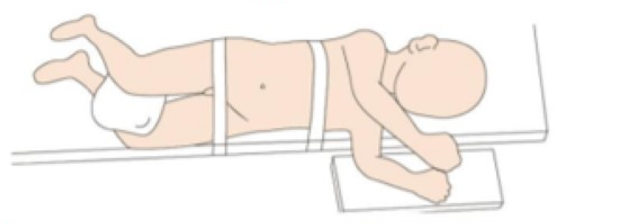
Figura 19 Posicionamento do paciente para laparoscopia do trato urinário superior
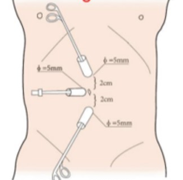
Figura 20 Posição do trocarte no trato urinário superior por via laparoscópica
Para a seleção da posição do paciente em cirurgias laparoscópicas do trato urinário superior assistidas por robô, seguimos quatro regras: primeiro, o paciente é colocado em posição renal para proporcionar espaço operatório e evitar a interferência com os braços do robô. Em segundo lugar, o paciente é colocado próximo à borda da mesa para diminuir a distância em relação ao assistente. Com o uso de rotação da mesa, preferimos a posição de decúbito lateral a 80˚. Por fim, o manejo da temperatura na sala operatória é muito importante. Devem ser utilizados máquina de ar aquecido e cobertores térmicos para cirurgias em lactentes.
Todos os portais foram posicionados sob visão direta, incluindo um trocarte para câmera de 8,5 mm, um trocarte de 8 mm e um trocarte de 5 mm. Um ou dois trocartes auxiliares adicionais de 3 mm foram colocados a 3 cm lateralmente ao ponto médio da linha de Pfannenstiel, para melhorar a eficiência da sutura
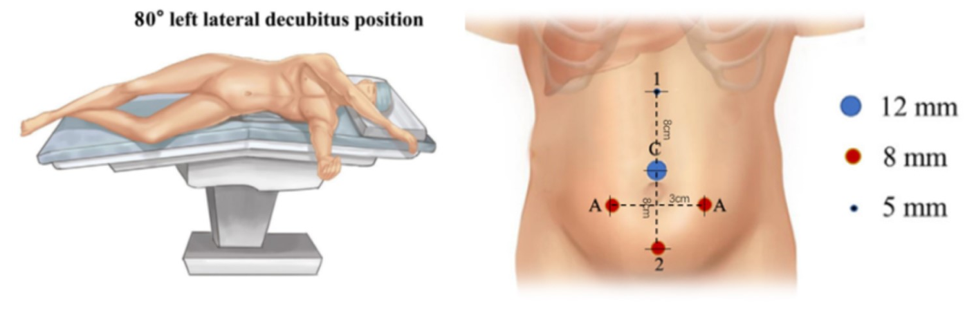
Figura 21 Posição do paciente e dos trocartes para cirurgia laparoscópica assistida por robô do trato urinário superior
Cirurgia do Trato Urinário Inferior
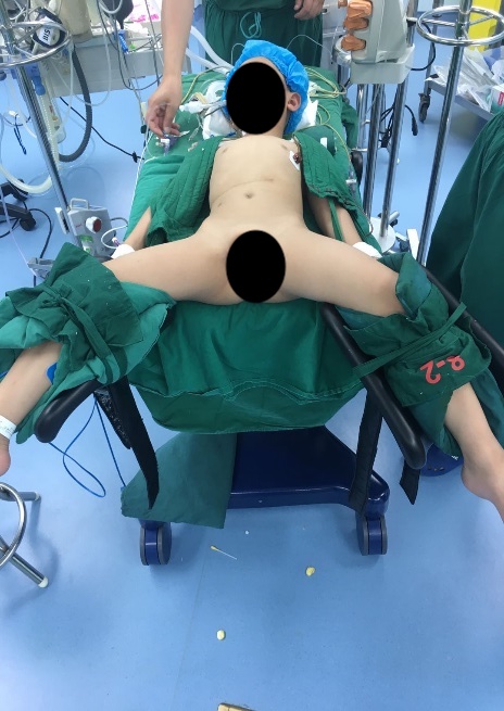
Figura 22 Posição de litotomia modificada para cirurgia do trato urinário inferior
Para cirurgias do trato urinário inferior, tanto laparoscópicas quanto laparoscópicas assistidas por robô, utilizamos a posição de litotomia modificada com a cabeça para baixo em 30–45˚. Os portais laparoscópicos ou robóticos são posicionados, incluindo um trocarte para a câmera através do umbigo, e dois trocartes adicionais colocados ao nível umbilical com distância de 4–6 cm entre eles.
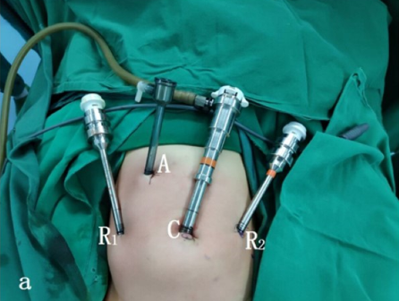
Figura 23 Posicionamento dos trocartes para cirurgia do trato urinário inferior
Aplicações da Técnica Laparoscópica e Robótica
Pieloplastia
A evidência bem estabelecida demonstrou que a pieloplastia laparoscópica ou a RALP não apenas tem taxas de sucesso iguais às da pieloplastia aberta, mas também apresenta as vantagens de ser minimamente invasiva, melhor cosmese, menor dor pós-operatória, menor tempo de internação e recuperação precoce. A pieloplastia desmembrada de Anderson-Hynes é o padrão-ouro para todas as abordagens.
Pieloplastia laparoscópica
Para a pieloplastia laparoscópica, tanto a via transperitoneal quanto a retroperitoneal podem proporcionar um campo cirúrgico satisfatório. No entanto, para a cirurgia assistida por robô, o espaço retroperitoneal é muito pequeno. Assim, apresentamos tanto a abordagem transperitoneal quanto a retroperitoneal para a pieloplastia laparoscópica e a abordagem transperitoneal para a RALP.
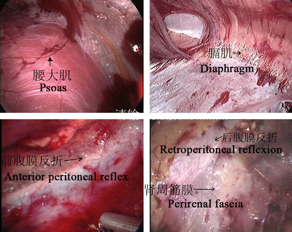
Figura 24 Marcadores anatômicos retroperitoneais
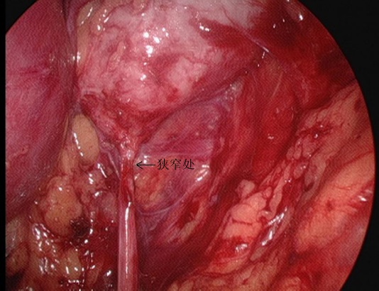
Figura 25 O segmento estenosado da UPJ em vista retroperitoneal
Abordagem Retroperitoneal
- Incidir longitudinalmente a pele 1,5–2,0 cm abaixo da ponta da 12ª costela na linha axilar posterior. A membrana tendínea na origem do músculo transverso do abdome e a fáscia toracolombar são separadas romamente com pinças vasculares para alcançar a região perirrenal. Um balão é colocado após a separação roma do espaço perirrenal com o dedo indicador para criar o espaço operatório retroperitoneal, e a pressão do pneumoperitônio é mantida em 8–14 mmHg, com média de 10 mm Hg.
- A fáscia perirrenal foi seccionada longitudinalmente com bisturi ultrassônico para expor a face dorsal do polo inferior do rim, e a pelve renal e o ureter proximal foram separados para revelar o local e a causa da estenose. Separar o dorso dos polos médio e inferior do rim, liberar e expor completamente a pelve renal e o ureter proximal, e esclarecer a OJUP.
- Incisar a pelve renal. Manter a porção medial da pelve incompletamente descolada e ainda conectada ao ureter, e abrir longitudinalmente o ureter até ultrapassar a estenose em 1,0 a 2,0 cm.
- Suturar o retalho da pelve renal ao ponto mais inferior do ureter com fio absorvível 5-0.
- Seccionar o ureter a aproximadamente 0,5 cm proximal ao segmento estenótico e completar a incisão da pelve renal para remover o segmento estenótico da JUP e parte da pelve renal dilatada.
- Sutura sequencial da parede posterior da anastomose com 1 ponto travado a cada 2 pontos
- Continuação da sutura da abertura do retalho excedente da pelve renal sem cortar os fios de sutura
- Colocação de um stent duplo J em linha através da anastomose.
- Sutura interrompida da parede anterior da anastomose.
- Na presença de compressão vascular ectópica, o vaso é colocado dorsal ao ureter da pelve renal para plicatura, a pressão do pneumoperitônio é reduzida, confirma-se que não há sangramento ativo no campo operatório, e deixa-se um dreno retroperitoneal por meio de uma agulha de trocarte na crista ilíaca para o fechamento da incisão.
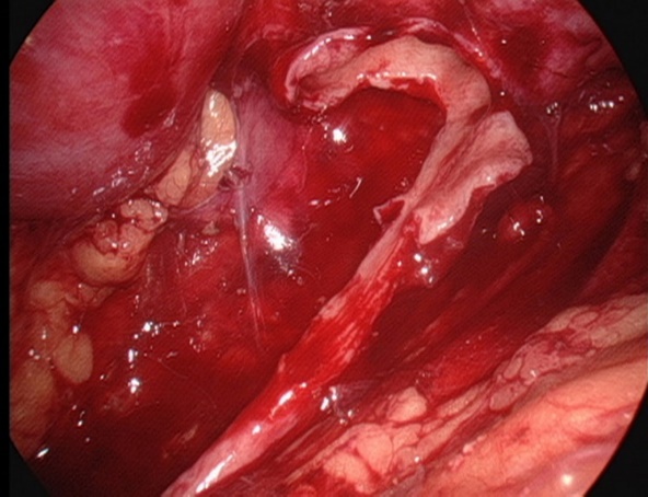
Figura 26 Mantenha a porção medial da pelve renal incompletamente descolada e ainda conectada ao uréter
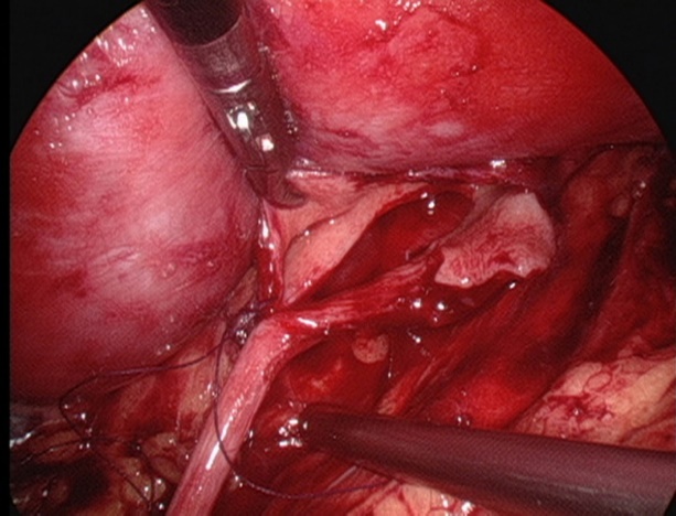
Figura 27 Suturar o ponto mais inferior do ureter
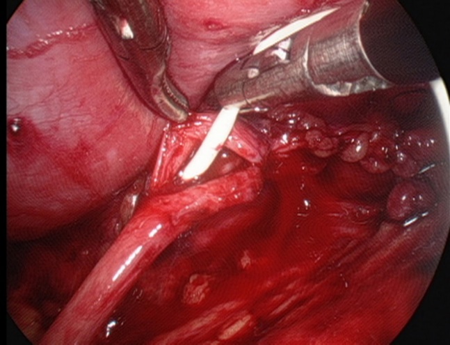
Figura 28 Colocação de um stent duplo J
Abordagem Transperitoneal
- Após estabelecer um acesso por trocarte normal, mantém-se a pressão pneumoperitoneal em 8–14 mmHg, com média de 10 mmHg.
- Abrir o peritônio lateral ao longo do lado lateral do sulco paracólico para liberar completamente o cólon, empurrar o cólon medialmente para identificar a veia gonadal e o ureter. Para pieloplastia à esquerda, abrir a área avascular ao longo do espaço mesentérico e, após liberar a gordura perirrenal, expor a pelve renal e o ureter superior.
- A pelve renal é totalmente liberada dos vasos hilares utilizando tração inferior e dissecção romba. Em seguida, liberar a pelve dorsalmente para ampliar a pelve renal e observar a presença de vasos vagais cruzando a junção ureteropélvica para esclarecer o local da estenose.
- O corno superior da pelve renal é suspenso à parede abdominal com fio mousse 2-0. Em seguida, cortar a pelve renal de posterior para inferior e, depois, para superior, para formar um formato de funil. Em seguida, cortar o ureter longitudinalmente para ultrapassar a estenose em 1 a 2 cm.
- Suturar o retalho da pelve renal ao ponto mais baixo do ureter com fio absorvível 5-0.
- Separar o ureter aproximadamente 0,5 cm distal ao segmento estenótico e completar ainda mais o corte da pelve renal para remover o segmento estenótico da UPJ e a pelve renal parcialmente dilatada
- Sutura sequencial da parede posterior da anastomose com 1 ponto de travamento a cada 2 pontos.
- Continuar suturando a abertura do retalho excedente da pelve renal sem cortar as suturas.
- Colocação de um stent duplo J.
- Sutura contínua da parede anterior da anastomose, hemostasia cuidadosa e meticulosa e irrigação do campo operatório com soro fisiológico morno.
- Sutura em pontos separados do peritônio lateral ou do espaço mesentérico.
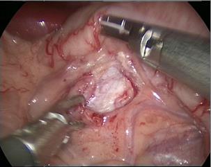
Figura 29 A abordagem transmesentérica
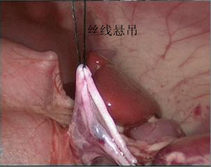
Figura 30 O corno superior da pelve renal está suspenso
Pieloplastia laparoscópica assistida por robô
- Nos casos do lado esquerdo, adotou-se a abordagem transmesentérica, enquanto a pelve renal dilatada estava localizada medial ao cólon descendente. Nos casos do lado direito, optamos pela abordagem pelo sulco paracólico.
- Em seguida, dissecamos cuidadosamente o ureter proximal e a pelve renal, preservando a vascularização ureteral.
- A pelve foi seccionada acima do tecido obstrutivo e aparada utilizando um ponto de suspensão percutâneo, para estabilizá-la e facilitar a anastomose.
- Após espatular o ureter distal, após a excisão do segmento obstrutivo, suturamos o ponto mais declive do segmento ureteral aperistáltico e a extremidade da pelve com uma sutura contínua 6-0 de PDS-II.
- Em seguida, a parede posterior do ureter foi fechada com sutura contínua. Antes de iniciar as anastomoses anteriores com uma segunda sutura contínua 6-0 PDS II, um stent ureteral duplo J (COOK, USI-512, Ireland) foi colocado de forma anterógrada.
- Por fim, fechamos o mesentério ou o peritônio com sutura absorvível 5-0.
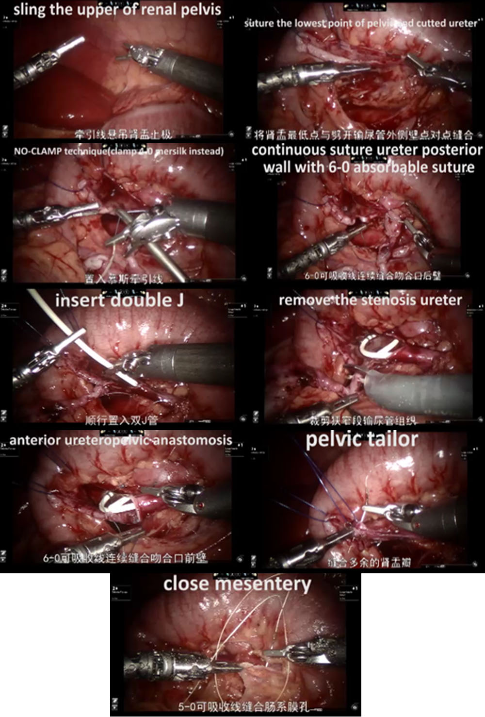
Figura 31 O procedimento de RALP
Reimplante ureteral
A reimplantação ureteral é o tratamento padrão-ouro para o refluxo vesicoureteral e a estenose ureteral. Tradicionalmente, esse procedimento tem sido realizado por via aberta. Diversas técnicas podem ser utilizadas: reimplantação intravesical de Cohen, reimplantação transvesical de Politano-Leadbetter, reimplantação extravesical de Lich-Gregoir. Todas as técnicas podem ser realizadas por via laparoscópica, laparoscopia pneumovesical ou abordagem robótica. Aqui apresentamos o procedimento de reimplantação de Cohen por laparoscopia pneumovesical (anastomose ureterovesical com túnel vesical submucoso transversal) e a reimplantação extravesical de Lich-Gregoir.
Estabelecimento pneumovesical
- O cistoscópio foi introduzido através da uretra. Em seguida, gás CO2 foi insuflado através do cistoscópio até que a bexiga ficasse dilatada ao nível umbilical. Foi realizada tração da bexiga cheia percutaneamente sob observação cistoscópica. Fixou-se o ápice da bexiga preenchida na posição subumbilical na linha média do abdome; a pele foi incisada na borda inferior da linha de tração. O trocarte foi puncionado imediatamente após a tração estar fixada. Um trocarte operatório de 3-5 mm foi colocado nos lados esquerdo e direito, respectivamente. Em seguida, o cistoscópio foi retirado. Gás CO2 foi insuflado via o trocarte oftalmoscópico.
- Localizar os orifícios ureterais bilaterais.
- Sutura-se um ponto de tração no orifício ureteral do lado acometido. Incisar a mucosa ao longo do orifício ureteral com alça de gancho elétrica. Liberar o ureter do segmento interno da parede vesical com bisturi elétrico ou bisturi ultrassônico, cuidadosamente. O ureter liberado é tracionado para dentro da bexiga por cerca de 5.0 cm até o segmento dilatado do ureter que possa ser trazido, sem tensão, até o ápice do orifício ureteral contralateral. Em paciente do sexo masculino, deve-se proteger o ducto deferente ao liberar o ureter.
- Fazer uma pequena abertura na junção do segmento distal dilatado do ureter com o segmento estenótico para drenar o líquido. Para diâmetro ureteral maior que 12 mm, deve-se realizar plicatura ou ressecção do ureter dilatado.
- Incisar a camada mucosa a cerca de 2.0 cm acima do orifício do ureter contralateral. Em seguida, separar a camada submucosa com tesoura ou pinça vascular e confeccionar um túnel submucoso até o orifício ureteral.
- Trazer o ureter para o lado oposto através do túnel submucoso, excisar o tecido da lesão estenótica no orifício ureteral, e fixar todo o ureter à mucosa vesical com suturas de Vicryl 5-0 ou 6-0 com 6-8 pontos, e 2 pontos na camada muscular da bexiga.
- Fechar a camada muscular vesical do orifício ureteral original com a camada muscular ureteral, com sutura de Vicryl 5-0
- Deixar um stent duplo J através do trocarte.
- Remover cada trocarte, suturar o subcutâneo e a pele.
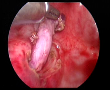
Figura 32 Liberar o ureter
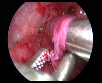
Figura 33 Faça um túnel submucoso até o orifício ureteral.
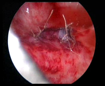
Figura 34 Feche o orifício ureteral original
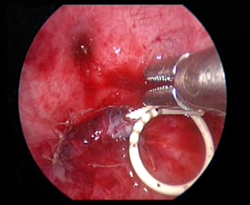
Figura 35 Deixe um cateter duplo J
Reimplantação Lich-Gregoir assistida por robô
- Abrir o peritônio lateral ao nível da artéria ilíaca externa pulsátil, identificar o ureter que cruza a artéria ilíaca externa e liberar o ureter tanto quanto possível até a junção ureterovesical para expor completamente a estenose ureteral.
- Encher a bexiga com 60 ml de solução salina para mantê-la levemente preenchida. Foi feita uma incisão de 5 cm na parede póstero-lateral da bexiga. Em seguida, incisar a bexiga até a submucosa da bexiga.
- Dissecar o ureter na junção ureterovesical, aparar o ureter distal ao tamanho normal. Ampliar a fissura da mucosa vesical nessa junção. Em seguida, suturar o ureter aparado à fissura da mucosa vesical com fio absorvível 6/0 para fixá-lo. Completar a anastomose da parede posterior e deixar o cateter duplo J no lugar para continuar a completar a parede anterior da anastomose (Nos casos de refluxo, inserir o cateter duplo J antes da cirurgia).
- Suturas absorvíveis foram utilizadas para fechar o peritônio na parede lateral da bexiga e o peritônio ao redor do ureter no segmento pélvico. O sistema robótico foi removido, foi colocado um tubo de drenagem e a incisão cutânea foi suturada.
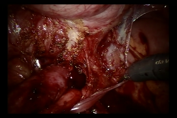
Figura 36 Liberar o ureter
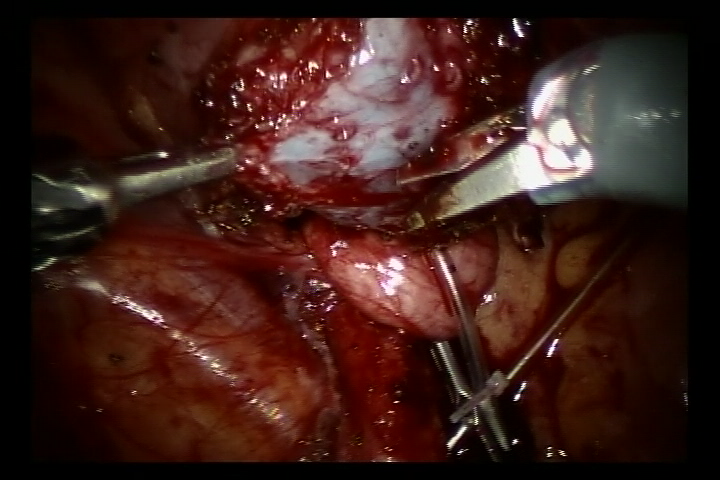
Figura 37 Incise a bexiga até a submucosa da bexiga
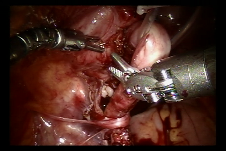
Figura 38 Suture ambos os lados da camada muscular esponjosa para formar um túnel submucoso
Rabdomiossarcoma da Bexiga
Rabdomiossarcoma (RMS) é o sarcoma de partes moles mais comum em crianças. Deve-se realizar cistectomia radical ou parcial para remover o tumor. Apresentamos aqui nossa experiência com cistectomia radical assistida por robô com reconstrução de neobexiga ortotópica sigmoide e reimplante ureteral bilateral (técnica de Politano-Leadbetter).
- Um portal de 10 mm foi colocado a cerca de 6 cm da sínfise púbica para a câmera. Dois portais robóticos de 8 mm para os braços robóticos #1 e #2 foram posicionados a 6 cm do portal da câmera na linha médio-clavicular, acima da espinha ântero-superior. Dois portais auxiliares de 5 mm foram posicionados na linha médio-clavicular direita, próximo, sob a margem costal.
- Após a ressecção radical cuidadosa e precisa do tumor vesical
-
e dos linfonodos pélvicos periféricos, capturamos cerca de 20 cm de cólon sigmoide e o detubulizamos em uma forma esférica para reconstruir a neobexiga que pode eventualmente
- comporta cerca de 100 mL.
- Em seguida, realizamos a reimplantação antirrefluxo (técnica de Politano-Leadbetter) dos ureteres, bilateralmente, por túnel submucoso
- Por fim, retiramos a peça cirúrgica pela incisão inguinal (linha do biquíni).
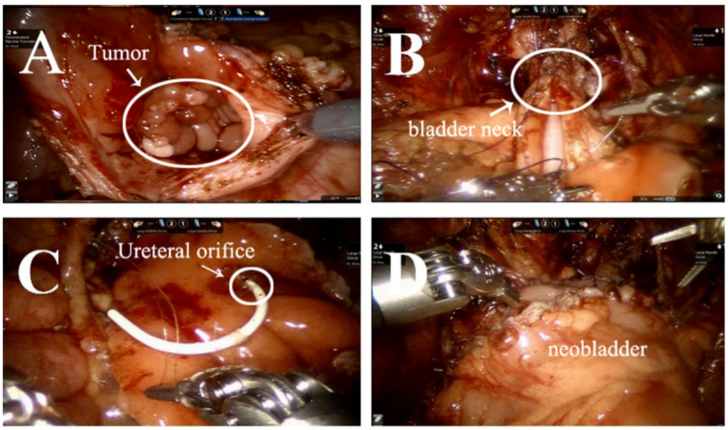
Figura 39 O procedimento de cistectomia radical com reconstrução de neobexiga ortotópica sigmoide com reimplante ureteral bilateral
Outras Aplicações
Também realizamos cirurgia laparoscópica assistida por robô para nefrectomia ou cirurgia poupadora de néfrons no tumor de Wilms, ressecção de neuroblastoma, capsulotomia prostática e reconstrução do ducto deferente. Nos casos complexos de hidronefrose, são realizadas substituições ureterais pela técnica de Yang-Monti, apendiculares ou com mucosa oral. Com a melhoria dos instrumentos e da tecnologia, o futuro da cirurgia minimamente invasiva é promissor.
Considerações
Para o reimplante, deve-se mobilizar o ureter em extensão suficiente para ressecar adequadamente a lesão ureteral e garantir, tanto quanto possível, uma anastomose sem tensão. Devido à ausência de feedback de força nos sistemas robóticos assistidos, deve-se evitar pinçamento excessivo dos tecidos ureterais, preservando os tecidos periureterais e a vascularização. Deve-se atentar para manter suturas simétricas ao realizar o reimplante ureterovesical, a fim de prevenir torção ou angulação do ureter.
Se o diâmetro do uréter exceder 1,5 cm no estado pós-miccional, ele deve ser seccionado; caso contrário, é difícil estabelecer uma estrutura antirrefluxo. O comprimento do túnel submucoso da bexiga deve ser cerca de 5 vezes o diâmetro do uréter, para manter uma pinça relativamente fixa como suporte e obter um efeito antirrefluxo satisfatório.
Na pieloplastia, a pelve renal deve ser dissecada mais amplamente, o que pode reduzir a tensão da anastomose, e o ureter proximal deve ser dissecado o mínimo possível para minimizar o pinçamento direto do ureter pelos instrumentos do sistema robótico e proteger o suprimento sanguíneo ureteral. A primeira sutura é a mais importante. Se o ureter da pelve renal for completamente separado e então anastomosado, é provável que ocorra distorção do ureter. Portanto, o eixo renal deve ser avaliado com precisão durante a cirurgia. e o retalho pélvico inferior. O ponto mais baixo da pelve renal deve ser anastomosado à parede lateral do ureter incisado longitudinalmente.
Referências
- WE. KJ. The evolution of laparoscopy and the revolution in surgery in the decade of the. 1990; 2 (4): 51.
- Cortesi N, Ferrari P, Zambarda E, Manenti A, Baldini A, Pignatti Morano F. Diagnosis of Bilateral Abdominal Cryptorchidism by Laparoscopy. Endoscopy 1976; 08 (01): 33–34. DOI: 10.1055/s-0028-1098372.
- Peters CA, Schlussel RN, Retik AB. Pediatric Laparoscopic Dismembered Pyeloplasty. J Urol 1995; 53 (6): 1962–1965. DOI: 10.1016/S0022-5347(01)67378-6.
- Blanco FC, Kane TD. Single-Port Laparoscopic Surgery in Children: Concept and Controversies of the New Technique. Minim Invasive Surg 2012; 2012 (232347): 1–5. DOI: 10.1155/2012/232347.
- Meininger DD, Byhahn C, Heller K, Gutt CN, Westphal K. Totally endoscopic Nissen fundoplication with a robotic system in a child. Surg Endosc 2001; 15 (11): 1360–1360. DOI: 10.1007/s00464-001-4200-3.
- OLSEN LH, JORGENSEN TM. Computer Assisted Pyeloplasty In Children: The Retroperitoneal Approach. J Urol 2004; 171 (6 Part 2): 2629–2631. DOI: 10.1097/01.ju.0000110655.38368.56.
- ATUG FATIH, WOODS MICHAEL, BURGESS SCOTTV, CASTLE ERIKP, THOMAS RAJU. Robotic Assisted Laparoscopic Pyeloplasty In Children. J Urol 2005; 174 (4 Part 1): 1440–1442. DOI: 10.1097/01.ju.0000173131.64558.c9.
- Lee RS, Retik AB, Borer JG, Peters CA. Pediatric Robot Assisted Laparoscopic Dismembered Pyeloplasty: Comparison With a Cohort of Open Surgery. Yearbook of Urology 2006; 2006 (2): 273–274. DOI: 10.1016/s0084-4071(08)70423-8.
- Hollis MV, Cho PS, Yu RN. Robot-Assisted Laparoscopic Pyeloplasty. Pediatric Robotic Urology 2015; 1: 109–121. DOI: 10.1007/978-1-60327-422-7_8.
- Andolfi C, Rodríguez VM, Galansky L, Gundeti MS. Infant Robot-assisted Laparoscopic Pyeloplasty: Outcomes at a Single Institution, and Tips for Safety and Success. Eur Urol 2021; 80 (5): 621–631. DOI: 10.1016/j.eururo.2021.06.019.
- Higganbotham C, Cook G, Rensing A. Bilateral Robot-Assisted Laparoscopic Orchiopexy for Undescended Testes. Urology 2021; 148 (314): 314. DOI: 10.1016/j.urology.2020.10.044.
- Rao PP. Robotic surgery: new robots and finally some real competition! World J Urol 2018; 36 (4): 537–541. DOI: 10.1007/s00345-018-2213-y.
- Peters BS, Armijo PR, Krause C, Choudhury SA, Oleynikov D. Review of emerging surgical robotic technology. Surg Endosc 2018; 32 (4): 1636–1655. DOI: 10.1007/s00464-018-6079-2.
Ultima atualização: 2025-09-21 13:35